


Instruction Manual
MS2401_Measurement_Microscope__Instruction_Manual-English.doc
Quick Overview
Finite. Total Magnification: 30X. 15X Eyepiece. 2X Objective. Eye Tube Angle: 45°. Eyepiece Field of View: Dia. 13mm. XY Stage Travel Distance: 2x2 in. XY-Axis Measurement Mode: Micrometer. Illumination Type: LED Dual Illuminated Light . Top Illumination: Oblique Top Light. Input Voltage: AC 100-240V 50/60Hz.
Suggested Applications
Industrial , Tool Making
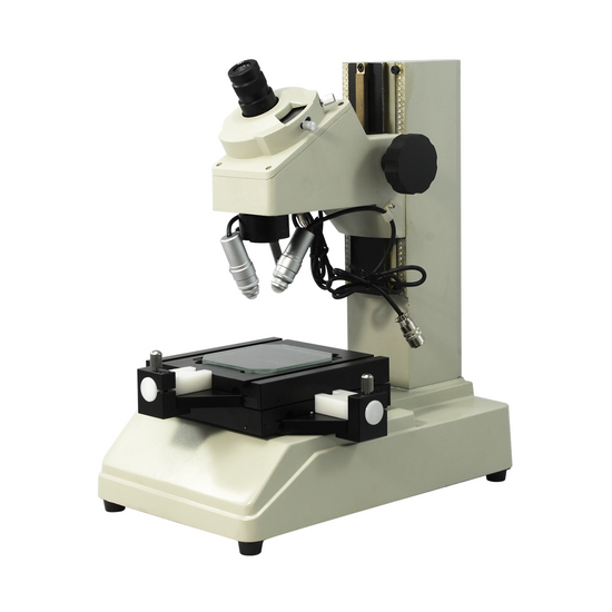
MS24010101 2x2" Tool Maker Measurement Microscope
Optical System Specifications
| Optical System | Finite |
| System Optical Magnification | 30X |
| Total Magnification | 30X |
| Standard Eyepiece | 15X Eyepiece |
| Standard Objective | 2X Objective |
| System Field of View | Dia. 0.14mm |
| System Working Distance | 67mm |
Microscope Eyepiece Tube
| Eye Tube Optical System | Finite |
| Eye Tube Type | For Compound Microscope |
| Eye Tube Angle | 45° |
| Eye Tube Rotatable | Fixed |
| Eye Tube Inner Diameter | Dia. 23mm |
| Eye Tube Diopter Adjustable | ±5° |
| Eye Tube Fixing Mode | Elastic Tube locking |
Eyepiece
| 15X Eyepiece ( Dia. 23/FN13) | |
| Eyepiece Type | Standard Eyepiece |
| Eyepiece Optical Magnification | 15X |
| Plan Eyepiece | Plan Eyepiece |
| Eyepiece Size for Eye Tube | Dia. 23mm |
| Eyepiece Field of View | Dia. 13mm |
| Surface Treatment | Electroplating Black |
| Material | Metal |
| Color | Black |
| Net Weight | 0.02kg (0.04lbs) |
Monocular Video Microscope Objective
| 2X Objective | |
| Objective Optical System | Finite |
| Objective Optical Magnification | 2X |
| Objective Type | Achromatic Objective |
| Objective Working Distance | 67mm |
| Numerical Aperture (N.A.) | N.A. 0.07 |
| Objective Screw Thread | M25x0.5mm |
| Objective Outer Diameter | Dia. 27mm |
| Surface Treatment | Electroplating Black |
| Material | Metal |
| Color | Black |
| Net Weight | 0.10kg (0.22lbs) |
| Applied Field | For MS2401 Series Microscope |
Microscope Stand
| Stand Height | 320mm |
| Base Type | Table Base |
| Base Shape | Rectangle |
| Base Dimensions | 330x200x70mm |
| Focus Mode | Manual |
| Focus Distance | 100mm |
| Coarse Focus Distance per Rotation | 26mm |
XY Measurement Stage
| 2x2" Measurement Manual Stage | |
| Mounting Holes Position | 140x70mm |
| Mounting Hole Dimensions | M4 |
| XY Stage Travel Distance | 2x2 in. |
| XY-Axis Drive Mode | Manual |
| Stage Platform Dimensions | 150x150mm |
| Stage Height | 44mm |
| Stage Backlight Window Size | 82x40mm |
| XY-Axis Measurement Mode | Micrometer |
| Micrometer Head Mount Size | Dia. 18mm |
| Surface Treatment | Electroplating Black |
| Material | Metal |
| Color | Black |
| Net Weight | 2.90kg (6.39lbs) |
Mechanical Micrometer Head
| 25mm/1" Mechanical Micrometer Head | |
| Digital Micrometer Head Measurement Range | 0-25mm (0-0.984 in. ) |
| Digital Micrometer Head Resolution | 2μm |
| Digital Micrometer Head Accuracy | 1μm |
| Digital Micrometer Head Spindle Diameter | Dia. 8mm |
| Mechanical Micrometer Head Graduation | 2μm |
| Surface Treatment | Polished Chrome |
| Material | Metal |
| Color | Black |
| Net Weight | 0.65kg (1.43lbs) |
Microscope Illuminator
| Illumination Type | LED Dual Illuminated Light |
| Top Illumination | Oblique Top Light |
| Top Illumination Type | LED |
| Bottom Illumination Type | LED |
Power Supply
| Input Voltage | AC 100-240V 50/60Hz |
| Output Voltage | DC 24V |
| Power Cord Connector Type | USA 3 Pins |
| Power Cable Length | 1.8m |
Environment Requirement
| Operating Temperature | -20~40°C(-4~104°F) |
| Operating Humidity | 80% |
Other Parameters
| Surface Treatment | Spray Paint |
| Material | Metal |
| Color | Wheat |
| Net Weight | 13.57kg (29.92lbs) |
| Dimensions | 330x200x390 (12.992x7.874x15.354 in. ) |
Series
| MS2401 | MS24010101 |
Technical Info
Instructions
Measurement MicroscopeClose Λ
| Measurement under the microscope is a kind of non-contact measurement, that is, the measurement tool uses the points, lines, circles, angles, areas, three-dimensional of the image and the complex geometric images of the measured object to measure and calculate without contacting the specimen. For measurements, different optical systems and different measurement methods can be used, from the simplest measurement with scales to tools such as optical measurement platforms, as well as relevant measurement software etc. Measurement microscope is the general term for microscopes with this type of function. Non-contact measurement can measure the data of some small and irregular objects that are not accessible by conventional measuring tools. Especially after amplification of the microscope, its measurement accuracy can be very high, and the error caused by the optical system is small or even negligible. Basic Hardware Requirements of the Measuring Microscope: Lens Requirements: For microscopic measurement, it must be ensured that the image surface of the objective lens is flat. Optical microscopic measurement is actually to measure the image of an object. The image must overcome the curvature of field brought about by the objective lens and the image distortion caused by astigmatism so as to make the measurement more accurate. Therefore, for microscopic measurement, plan objective is recommended; for large-area long-distance measurement, the impact of perspective error also needs to overcome, for which, telecentric objective lens should be used. For microscopic measurement, single light path microscope is generally used, such as metallurgical microscope; for continuous magnification, video zoom lens should be used. Because the two optical paths of the dual light-path stereo microscope have an angle of 12 degrees, on each optical path there has actually a 6 degree inclination angle from the vertical angle, in such a case, the measurement will cause error. If the microscope is continuously zoomed, the main multiple points that need to be zoomed in should have magnification detent. Light Source Requirements: The light source for microscopic measurement should be uniform on the image plane of the field of view, and the bottom light should preferably use parallel light to make the outline and feature points clear. In theory, for microscopic measurement, it is best to use monochromatic light to reduce the effect of chromatic aberration, and therefore red light with the longest wavelength in the visible light is often used in measurement. Platform Requirements: Using optical measurement platform, it is possible to measure some large objects that exceed the microscope's field of view, and can achieve an accuracy of micron or even much smaller. The platform requires that the table plane should be of sound flatness, and maintains stable and leveling during movement. Moreover, the platform needs to have good rigidity, is not deformed or displaced itself, ensuring repeated measurement accuracy. Other Simple Measurement Methods: With the simple mechanism on the microscope, simple measurements and calculations can be performed on some observed objects that are not easy to use contact measurement. In addition to eyepiece reticle and objective micrometer measurement that we are familiar with, there are also other simple methods: for example, using the scale on the microscope stage, its accuracy can reach 0.1mm, which can measure the length of the measured object and roughly calculate its area; Using fine-tuning hand wheel mechanism of the microscope, calculate the height of the object to be observed by converting the fine-tuning number of revolutions into focusing stroke; using the rotating stage and the goniometer eyepiece, measure the angle etc. Calibration: Since the measurement is performed under the microscope on the image after the object is enlarged, it is therefore necessary to add a scale on the observed object so as to determine the actual size. The scale of a general microscope is called microscope micrometer, used to compare the actual size of the object or, as a scale6, to record to the measurement system. Generally, the reticle measurement on the eyepiece of the microscope is between 0.2 μm ~ 25 mm, of which 0.2 μm is the resolution of optical microscope, and 25 mm is the maximum diameter of the microscope field of view. The effect of the magnification should be subtracted from the measured dimensions. Or for the eyepiece reticle, it is necessary to coordinate with the objective micrometer to calibrate under the microscope, convert the grid value on the eyepiece reticle to the length on the objective micrometer, and then measure. In the XYZ measurement platform, the error caused by the measurement in the horizontal and vertical directions of the platform and the error caused in the repeated positioning accuracy by the rigidity of the platform should all be calibrated. For measuring microscopes and scales, the calibration of their system or measuring components is usually conducted by relevant agencies within a certain time frame to make the measurement more accurate. On the Error of Optical measurement: The reason for the error of measurement is multi-faceted. From the theoretical point of view, for rough measurement using eyepiece reticle to zoom in through the objective lens of the microscope, the influence of the error of system magnification is relatively large, and because of the geometric magnification error of the optical lens, the objective lens of ordinary microscope can achieve plus or minus 5%. Measuring with a scale on the objective lens, the problem of error of the measurement result caused by the magnification error of the objective lens can be theoretically solved. Measurement using mechanical platforms, regardless of the drive and measurement scale used, aside from the theoretical error caused by the depth of field of the objective lens, it mainly depends on the measurement reading mechanism, such as gratings, micrometers and dial gauges etc. However, the rigidity of the platform, the flatness of the platform surface, and the level of platform movement will still affect the measurement results. Therefore, finding the problem can improve effectively the accuracy requirements when using even a very economical equipment system. |
FiniteClose Λ
| Microscopes and components have two types of optical path design structures. One type is finite optical structural design, in which light passing through the objective lens is directed at the intermediate image plane (located in the front focal plane of the eyepiece) and converges at that point. The finite structure is an integrated design, with a compact structure, and it is a kind of economical microscope. Another type is infinite optical structural design, in which the light between the tube lens after passing the objective lens becomes "parallel light". Within this distance, various kinds of optical components necessary such as beam splitters or optical filters call be added, and at the same time, this kind of design has better imaging results. As the design is modular, it is also called modular microscope. The modular structure facilitates the addition of different imaging and lighting accessories in the middle of the system as required. The main components of infinite and finite, especially objective lens, are usually not interchangeable for use, and even if they can be imaged, the image quality will also have some defects. The separative two-objective lens structure of the dual-light path of stereo microscope (SZ/FS microscope) is also known as Greenough. Parallel optical microscope uses a parallel structure (PZ microscope), which is different from the separative two-object lens structure, and because its objective lens is one and the same, it is therefore also known as the CMO common main objective. |
System Optical MagnificationClose Λ
| The magnification of the objective lens refers to the lateral magnification, it is the ratio of the image to the real size after the original image is magnified by the instrument. This multiple refers to the length or width of the magnified object. System optical magnification is the product of the eyepiece and the objective lens (objective lens zoom set) of the optical imaging part within the system. Optical magnification = eyepiece multiple X objective lens/objective lens set The maximum optical magnification of the microscope depends on the wavelength of the light to which the object is illuminated. The size of the object that can be observed must be greater than the wavelength of the light. Otherwise, the light cannot be reflected or transmitted, or recognized by the human eye. The shortest wavelength of ultraviolet light is 0.2 microns, so the resolution of the optical microscope in the visible range does not exceed 0.2 microns, or 200 nanometers. This size is converted to the magnification of the microscope, and it is the optical magnification of 2000X. Usually, the compound microscope can achieve 100X objective lens, the eyepiece is 20X, and the magnification can reach 2000X. If it is bigger, it will be called "invalid magnification", that is, the image is large, but the resolution is no longer increased, and no more details and information can be seen. |
Total MagnificationClose Λ
| Total magnification is the magnification of the observed object finally obtained by the instrument. This magnification is often the product of the optical magnification and the electronic magnification. When it is only optically magnified, the total magnification will be the optical magnification. Total magnification = optical magnification X electronic magnification Total magnification = (objective X photo eyepiece) X (display size / camera sensor target ) |
System Field of ViewClose Λ
| Field of View, is also called FOV. The field of view, or FOV, refers to the size of the object plane (i.e., the plane of the point of the observed object perpendicular to the optical axis), or of its conjugate plane (i.e., object to primary image distance), represented by a line value. System field of view is the size of the actual diameter of the image of the terminal display device of the instrument, such as the size of the image in the eyepiece or in the display. Field of view number refers to the diameter of the field diaphragm of the objective lens, or the diameter of the image plane formed by the field diaphragm. Field of view number of objective lens = field of view number of eyepiece / (objective magnification / mechanical tube length) Large field of view makes it easy to observe the full view and more range of the observed object, but the field of view (FOV) is inversely proportional to the magnification and inversely proportional to the resolution, that is, the larger the field of view, the smaller the magnification, and also the lower the resolution of the object to be observed. There are usually two ways to increase the field of view, one is to replace with an objective lens of a smaller multiple, or to replace with an eyepiece of a smaller multiple. |
System Working DistanceClose Λ
| Working distance, also referred to as WD, is usually the vertical distance from the foremost surface end of the objective lens of the microscope to the surface of the observed object. When the working distance or WD is large, the space between the objective lens and the object to be observed is also large, which can facilitate operation and the use of corresponding lighting conditions. In general, system working distance is the working distance of the objective lens. When some other equipment, such as a light source etc., is used below the objective lens, the working distance (i.e., space) will become smaller. Working distance or WD is related to the design of the working distance of the objective lens. Generally speaking, the bigger the magnification of the objective lens, the smaller the working distance. Conversely, the smaller the magnification of the objective lens, the greater the working distance. When it is necessary to change the working distance requirement, it can be realized by changing the magnification of the objective lens. |
Eye Tube AngleClose Λ
| Usually the Microscope Eyetube is 45°, some is 30°, Tiltable Eyetube Angle design of a microscope is also known as the ergonomics microscope. 0-30° or 0-45° is an ergonomic design. When the mechanical tube length / focal length of the tube of the microscope is relatively big, the microscope is relatively high, and the user's height or the seat of the work desk is not suitable, long-term use of microscope may cause sitting discomfort. Eyepiece tube with variable angle can freely adjust the angle without lowering the head. Especially when it is close to 0 degree and the human eye is close to horizontal viewing, long-time or long-term use can avoid fatigue damage to the cervical vertebra. |
Eye Tube Diopter AdjustableClose Λ
| For most people, their two eyes, the left and the right, have different vision; for the eyepiece tube, the eyepoint height of the eyepiece can be adjusted to compensate for the difference in vision between the two eyes, so that the imaging in the two eyes is clear and consistent. The range of adjustment of the eyepiece tube is generally diopter plus or minus 5 degrees, and the maximum differential value between the two eyepieces can reach 10 degrees. Monocular adjustable and binocular adjustable: some microscopes have one eyepiece tube adjustable, and some have two eyepiece tubes adjustable. First, adjust one eyepiece tube to the 0 degree position, adjust the microscope focusing knob, and find the clear image of this eyepiece (when the monocular adjustable is used, first adjust the focusing knob to make this eyepiece image clear), then adjust the image of another eyepiece tube (do not adjust the focusing knob again at this time), repeatedly adjust to find the clear position, then the two images are clear at the same time. For this particular user, do not adjust this device anymore in the future. As some microscopes do not have the vision adjustment mechanism for the eyepiece tube, the vision of the two eyes are adjusted through the eyepiece adjustable. |
Eyepiece Optical MagnificationClose Λ
| Eyepiece optical magnification is the visual magnification of the virtual image after initial imaging through the eyepiece. When the human eye observes through the eyepiece, the ratio of the tangent of the angle of view of the image and the tangent of the angle of view of the human eye when viewing or observing the object directly at the reference viewing distance is usually calculated according to 250 mm/focal length of eyepiece. The standard configuration of a general microscope is a 10X eyepiece. Usually, the magnification of the eyepiece of compound microscope is 5X, 8X, 10X, 12.5X, 16X, 20X. As stereo microscope has a low total magnification, its eyepiece magnification generally does not use 5X, but can achieve 25X, 30X and other much bigger magnification. |
Eyepiece Field of ViewClose Λ
| The eyepiece field of view is the diameter of the field diaphragm of the eyepiece, or the diameter of the image plane of the field diaphragm imaged by the field diaphragm. The diameter of a large field of view can increase the viewing range, and see more detail in the field of view. However, if the field of view is too large, the spherical aberration and distortion around the eyepiece will increase, and the stray light around the field of view will affect the imaging effect. |
Objective Optical MagnificationClose Λ
| The finite objective is the lateral magnification of the primary image formed by the objective at a prescribed distance. Infinite objective is the lateral magnification of the real image produced by the combination of the objective and the tube lens. Infinite objective magnification = tube lens focal length (mm) / objective focal length (mm) Lateral magnification of the image, that is, the ratio of the size of the image to the size of the object. The larger the magnification of the objective, the higher the resolution, the smaller the corresponding field of view, and the shorter the working distance. |
Objective TypeClose Λ
| In the case of polychromatic light imaging, the aberration caused by the light of different wavelengths becomes chromatic aberration. Achromatic aberration is to correct the axial chromatic aberration to the two line spectra (C line, F line); apochromatic aberration is to correct the three line spectra (C line, D line, F line). The objective is designed according to the achromaticity and the flatness of the field of view. It can be divided into the following categories. Achromatic objective: achromatic objective has corrected the chromatic aberration, spherical aberration, and comatic aberration. The chromatic portion of the achromatic objective has corrected only red and green, so when using achromatic objective, yellow-green filters are often used to reduce aberrations. The aberration of the achromatic objective in the center of the field of view is basically corrected, and as its structure is simple, the cost is low, it is commonly used in a microscope. Semi-plan achromatic objective: in addition to meeting the requirements of achromatic objective, the curvature of field and astigmatism of the objective should also be properly corrected. Plan achromatic objective: in addition to meeting the requirements of achromatic objectives, the curvature of field and astigmatism of the objective should also be well corrected. The plan objective provides a very good correction of the image plane curvature in the field of view of the objective, making the entire field of view smooth and easy to observe, especially in measurement it has achieved a more accurate effect. Plan semi-apochromatic objective: in addition to meeting the requirements of plan achromatic objective, it is necessary to well correct the secondary spectrum of the objective (the axial chromatic aberration of the C line and the F line). Plan apochromatic objective: in addition to meeting the requirements of plan achromatic objective, it is necessary to very well correct the tertiary spectrum of the objective (the axial chromatic aberration of the C line, the D line and the F line) and spherochromatic aberration. The apochromatic aberration has corrected the chromatic aberration in the range of red, green and purple (basically the entire visible light), and there is basically no limitation on the imaging effect of the light source. Generally, the apochromatic aberration is used in a high magnification objective. |
Objective Working DistanceClose Λ
| The objective working distance is the vertical distance from the foremost surface end of the objective of the microscope to the object surface to be observed. Generally, the greater the magnification, the higher the resolution of the objective, and the smaller the working distance, the smaller the field of view. Conversely, the smaller the magnification, the lower the resolution of the objective, and the greater the working distance, and greater the field of view. High-magnification objectives (such as 80X and 100X objectives) have a very short working distance. Be very careful when focusing for observation. Generally, it is after the objective is in position, the axial limit protection is locked, then the objective is moved away from the direction of the observed object. The relatively greater working distance leaves a relatively large space between the objective and the object to be observed. It is suitable for under microscope operation, and it is also easier to use more illumination methods. The defect is that it may reduce the numerical aperture of the objective, thereby reducing the resolution. |
Numerical Aperture (N.A.)Close Λ
| Numerical aperture, N.A. for short, is the product of the sinusoidal function value of the opening or solid angle of the beam reflected or refracted from the object into the mouth of the objective and the refractive index of the medium between the front lens of the objective and the object. Simply speaking, it is the magnitude of the luminous flux that can be brought in to the mouth of the objective adapter, the closer the objective to the specimen for observation, the greater the solid angle of the beam entering the mouth of the objective adapter, the greater the N.A. value, and the higher the resolution of the objective. When the mouth of the objective adapter is unchanged and the working distance between the objective and the specimen is constant, the refractive index of the medium will be of certain meaning. For example, the refractive index of air is 1, water is 1.33, and cedar oil is 1.515, therefore, when using an aqueous medium or cedar oil, a greater N.A. value can be obtained, thereby improving the resolution of the objective. Formula is: N.A. = refractive index of the medium X sin solid angle of the beam of the object entering the front lens frame of the objective/ 2 Numerical aperture of the objective. Usually, there is a calculation method for the magnification of the microscope. That is, the magnification of the microscope cannot exceed 1000X of the objective. For example, the numerical aperture of a 100X objective is 1.25, when using a 10X eyepiece, the total magnification is 1000X, far below 1.25 X 1000 = 1250X, then the image seen in the eyepiece is relatively clear; if a 20X eyepiece is used, the total magnification will reach 2000X, much higher than 1250X, then eventhoughthe image actually seen by the 20X eyepiece is relatively large, the effect will be relatively poor. |
Objective Screw ThreadClose Λ
| For microscopes of different manufacturers and different models, the thread size of their objectives may also be different. In general, the objective threads are available in two standard sizes, allowing similar objectives between different manufacturers to be used interchangeably. One is the British system: RMS type objective thread: 4/5in X 1/36in, One is metric: M25 X 0.75mm thread. |
XY Measurement StageClose Λ
| The XY measurement stage refers to the stage with a measuring mechanism in the XY horizontal direction, and it requires that the stage has relatively high accuracy. The stage not only has a flatness requirement on the surface, but also needs to ensure that in measurement the XY plane is always in a horizontal position during the movement. For the XY measurement stage, especially when observing and measuring the observed object beyond the field of view, the stage can be moved, and reading can be carried out through an externally attached measurement device to measure accurately large sized objects. XY Stage Measurement Method For XY measurements, a crosshair is required within the measurement field of view for aiming and positioning. The crosshair can be obtained by various means, generally on the eyepiece, using the preset reticle method, which is the simplest method. When using the monitor screen for measurement, a cross reticle can also be used, which is placed in the photographic eyepiece optical system. This method is simple and practical, the reticle is relatively clear, and various patterns of reticle can be used. It is also convenient to adjust the alignment angle of the reticle in the eyepiece. At present, more and more measurements use the crosshair function in the camera. The crosshairs are displayed by splicing the pixels of the same color, and even the color can be selected so that it is clearly distinguished from the background pattern, making the crosshairs more conspicuous and easy to operate. Some cameras have crosshairs that can also add multiple sets of lines, and can move horizontally and vertically so as to combine a variety of rectangular patterns of different sizes. One can apply and mark the position and size of the observed specimens. In industrial processing, it has the profilometer and projector functions. In addition to the camera to obtain the crosshair, there is also method of using a crosshair generator, display and other devices to obtain crosshair. During measurement, first place the object to be measured on the center position of the field of view of the stage, adjust the clear image, open the crosshair, and then move the object to be measured to the starting position to be measured, so that the center intersection of the crosshair is aligned with the said position, turn on the scale 0 position (or note the reading position), then move the object to be measured in the X or Y direction until the end point of the measurement position, then stops, and finally read through the measuring scale. Measurement error in XY horizontal direction During measurement, aim at the starting point of the object to be measured through the eyepiece or the cross positioning on the display, then move the stage, so that the stage is moved to the end point in the horizontal axial movement. At this time, it is necessary to ensure that the distance between the two points is the actual distance of the horizontal direction. If the stage is tilted, an angle is created between the horizontal direction and the tilted or oblique direction. The numerical value we read is actually the length of a diagonal line, thereby causing error. For XY stage measurement, it is necessary to use a high-magnification objective as much as possible. The objective lens has a certain depth of field. The smaller the objective lens is, the larger the depth of field will be. The large depth of field cannot reflect the image blurring conditions caused by the up and down misalignment when the stage moves horizontally: the bigger the objective magnification, the smaller the depth of field. When the stage is not flat and moves out of the depth of field range, the image will be out of focus and becomes blurred, indicating that the stage is in a non-horizontal position, and the accuracy of the measurement at this time will be higher. In principle, the depth of field range of the objective of the microscope is the minimum error range of the flatness of the platform stage. For XY horizontal measurement, when measuring objects with shorter lengths, this error is very small, even negligible. If the measured object is relatively long, the bigger the angle at which the stage is tilted, the greater the differential value between the oblique line of the measured image and the actual horizontal line segment of the object, and also the bigger the accumulated error will be. Because big stage has a bigger accumulated error, when measuring a relatively bigger length, it is necessary to calibrate the error within the stage system in advance. In measurement using computer software, the value of this accumulated error can be input into the measurement result for correction. Therefore, it must be ensured that the stage is always in a horizontal state in movement, which is the most basic requirement in optical measurement. Ways to adjust the level of the XY stage: 1. Use a cross reticle in the eyepiece or display. 2. Select an objective with the largest magnification in the microscope system, and place a calibrated line ruler on the stage (a long transparent glass ruler for calibration). The marked front of the line ruler is below the ruler, near the side of the stage countertop. 3. Overlap the starting point of the line ruler with the starting position on one side of the stage; adjust the focus, ensure that the objective is aligned with the starting position image of the line scale to obtain the clearest image. 4. Move the X direction of the stage, so that the stage moves along the direction of the line ruler, and at the same time observe whether the grid image of the line ruler is clear, and record the blurred position of the image until the end position. After completion, do the side of the Y direction. 5. Among the above results, the unclear position is the position where the stage is not flat. If the stage is unable to maintain horizontal, after the initial position is focus adjusted to get a clear image, the image will become more and more blurred, and in most cases, the stage is tilted to one side (up or down). To solve this problem, adjust the height of the four feet of the stage, or adjust the height position of the screws at the four corners of the bottom glazing of the stage center to keep the stage horizontal. In general, adjusting the stage horizontal can adjust the height of the position of the anchor screw of the stage, or use a very thin shim (Shim) to adjust. Sometimes, it is also necessary to adjust the perpendicularity of the optical axis of the microscope. Use the screw that fixes the microscope to top move the microscope, to make it shift in the vertical direction, keeping the microscope in a vertical position. Using a line ruler can also calibrate whether the distance traveled by the line ruler at each grid value for measurement is consistent with the distance read by the stage drive (for example, the reading from the micrometer or the digital display), thereby calibrating the error of the stage movement accuracy. Such errors are often caused by the empty return of the stage drive or the insufficient of stage stiffness etc. If line ruler is not used and the stage surface is observed directly, the above results can also be obtained. Also, when the stage surface is moved to each position, that whether the surface of the stage is uneven when processing can be displayed through clear or blurred image position, and can also observe whether the flatness of the stage plane itself is within the allowable range of the depth of field of the objective. |
Stage Backlight Window SizeClose Λ
| Stage backlight window size refers to the size of the window through which the transmitted light passes under the stage on the XY table plane of the stage. This window is usually covered with a piece of glass. For some stages with accuracy requirements in the XY horizontal direction, the horizontal plane of the glass can be adjusted by the height of the screws on the four corners below, and the consistency with the height of the stage plane is guaranteed. |
XY-Axis Measurement ModeClose Λ
| The XY-axis measurement mode refers to the way the scale used when measuring the XY axis of the stage. For different system, the choice is also different according to the different accuracy and operation requirements, such as mechanical micrometer, capacitance digital display, encoder and so on. |
Mechanical Micrometer HeadClose Λ
| The micrometer head can be divided into two types: mechanical micrometer, and electronic micrometer. Mechanical type is a micrometer head that measures the length of displacement through the thread principle. When used in platform, micrometer head has two functions, one is to generate displacement as the drive platform, and the other is to measure the reading in the displacement. The mechanical micrometer head is a micrometer adjustment device that measures the length using the thread principle and has a measurement resolution of up to the micron level with an accuracy of 0.01 mm.. Mechanical micrometer head is also called micrometer head, spiral micrometer, micrometer. In experiment, micrometer head is a tool used to generate displacement and indicate the amount of the displacement. The mounting sleeve of the micrometer head is to facilitate fixed mounting on the stand base. The main ruler on the axial sleeve has two rows of scale lines: the row that is marked with number is the whole millimeter line (1mm/grid); the other row is the half mm line (0.5mm/grid); the circumferential surface of the front part of the micrometer tube is engraved with 50 equal mark lines (0.01 mm/gird). When the micrometer tube or the fine focus knob is rotated by hand, the measuring rod advances or retreats along the direction of the axis. For every 1 gird rotated by the micrometer tube, the measuring rod moves a small displacement of 0.01 mm along the axial direction, which is also called the graduation value of the micrometer head. The micrometer head reading method is to read the scale value exposed on the main ruler of the sleeve first, pay attention to the half-millimeter line; then read the numerical value on the micrometer tube aligned with the horizontal line of the main ruler, and 1/10 graduation can be estimated. |
PackagingClose Λ
| After unpacking, carefully inspect the various random accessories and parts in the package to avoid omissions. In order to save space and ensure safety of components, some components will be placed outside the inner packaging box, so be careful of their inspection. For special packaging, it is generally after opening the box, all packaging boxes, protective foam, plastic bags should be kept for a period of time. If there is a problem during the return period, you can return or exchange the original. After the return period (usually 10-30 days, according to the manufacturer’s Instruction of Terms of Service), these packaging boxes may be disposed of if there is no problem. |
Optical Data
| Microscope Optical Data Sheet | ||||
| P/N | Objective | Objective Working Distance | Eyepiece | |
| MS24011202 (15X Dia. 13mm) | ||||
| Magnification | Field of View(mm) | |||
| MS24011301 | 2X | 67mm | 30X | 6.5mm |
| MS24011302 | 5X | 33mm | 75X | 2.6mm |
| MS24011303 | 10X | 14mm | 150X | 1.3mm |
| 1. Magnification=Objective Optical Magnification * Body Magnification * Eyepiece Optical Magnification | ||||
| 2. Field of View=Eyepiece Field of View /(Objective Optical Magnification*Body Magnification) | ||||
| 3. The Darker background items are Standard items, the white background items are optional items. | ||||
| Video Microscope Optical Data Sheet | ||
| P/N | Objective | Coupler |
| MS02041401 (0.3X) | ||
| Magnification | ||
| MS24011301 | 2X | 0.6X |
| MS24011302 | 5X | 1.5X |
| MS24011303 | 10X | 3X |
| 1. Magnification=Objective Optical Magnification * Body Magnification * Coupler Magnification | ||
| Camera Image Sensor Specifications | |||
| No. | Camera Image Sensor Size | Camera image Sensor Diagonal | |
| (mm) | (inch) | ||
| 1 | 1/4 in. | 4mm | 0.157" |
| 2 | 1/3 in. | 6mm | 0.236" |
| 3 | 1/2.8 in. | 6.592mm | 0.260" |
| 4 | 1/2.86 in. | 6.592mm | 0.260" |
| 5 | 1/2.7 in. | 6.718mm | 0.264" |
| 6 | 1/2.5 in. | 7.182mm | 0.283" |
| 7 | 1/2.3 in. | 7.7mm | 0.303" |
| 8 | 1/2.33 in. | 7.7mm | 0.303" |
| 9 | 1/2 in. | 8mm | 0.315" |
| 10 | 1/1.9 in. | 8.933mm | 0.352" |
| 11 | 1/1.8 in. | 8.933mm | 0.352" |
| 12 | 1/1.7 in. | 9.5mm | 0.374" |
| 13 | 2/3 in. | 11mm | 0.433" |
| 14 | 1/1.2 in. | 12.778mm | 0.503" |
| 15 | 1 in. | 16mm | 0.629" |
| 16 | 1/1.1 in. | 17.475mm | 0.688" |
| Digital Magnification Data Sheet | ||
| Image Sensor Size | Image Sensor Diagonal size | Monitor |
| Screen Size (24in) | ||
| Digital Zoom Function | ||
| 1/3 in. | 6mm | 101.6 |
| 1. Digital Zoom Function= (Screen Size * 25.4) / Image Sensor Diagonal size | ||
| Microscope Optical and Digital Magnifications Data Sheet | ||||||||||
| Objective | Coupler | Camera | Monitor | Video Microscope Optical Magnifications | Digital Zoom Function | Total Magnification | Field of View (mm) | |||
| PN | Magnification | PN | Magnification | Image Sensor Size | Image Sensor Diagonal size | Screen Size | ||||
| MS24011301 | 2X | MS02041401 | 0.3X | 1/3 in. | 6mm | 24in | 0.6X | 101.6 | 60.96X | 10mm |
| MS24011302 | 5X | MS02041401 | 0.3X | 1/3 in. | 6mm | 24in | 1.5X | 101.6 | 152.4X | 4mm |
| MS24011303 | 10X | MS02041401 | 0.3X | 1/3 in. | 6mm | 24in | 3X | 101.6 | 304.8X | 2mm |
| 1. Video Microscope Optical Magnifications=Objective Optical Magnification * Body Magnification * Coupler Magnification | ||||||||||
| 2. Digital Zoom Function= (Screen Size * 25.4) / Image Sensor Diagonal size | ||||||||||
| 3. Total Magnification= Video Microscope Optical Magnifications * (Screen Size * 25.4) / Image Sensor Diagonal size | ||||||||||
| 4. Field of View (mm)= Image Sensor Diagonal size / Video Microscope Optical Magnifications | ||||||||||
| Contains | ||||||||||||||||
| Parts Including | ||||||||||||||||
| ||||||||||||||||
| Desiccant Bag | 1 Bag | |||||||||||||||
| Dust Cover | 1pc | |||||||||||||||
| Spare Bulb | 2pc | |||||||||||||||
| Product Instructions/Operation Manual | 1pc | |||||||||||||||


| Packing | |
| Packaging Type | Carton Packaging |
| Packaging Material | Corrugated Carton |
| Packaging Dimensions(1) | 41x31.5x47.5cm (16.142x12.402x18.701″) |
| Inner Packing Material | Plastic Bag |
| Ancillary Packaging Materials | Expanded Polystyrene |
| Gross Weight | 15.56kg (34.30lbs) |
| Minimum Packaging Quantity | 1pc |
| Transportation Carton | Carton Packaging |
| Transportation Carton Material | Corrugated Carton |
| Transportation Carton Dimensions(1) | 41x31.5x47.5cm (16.142x12.402x18.701″) |
| Total Gross Weight of Transportation(kilogram) | 15.56 |
| Total Gross Weight of Transportation(pound) | 34.30 |


