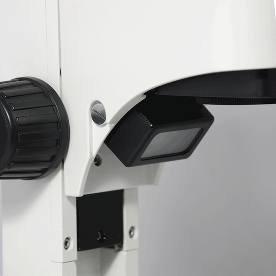
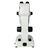
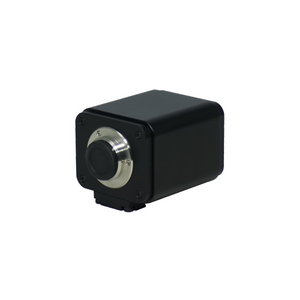
Quick Overview
Finite. Total Magnification: 8-35X. 10X Adjustable Eyepiece. 1X Built-in Objective. Eye Tube Angle: 60°. Eyepiece Field of View: Dia. 22mm. Illumination Type: LED Dual Illuminated Light . Top Illumination: Oblique Top Light. CMOS. 5.0 Megapixels. HDMI / USB 2.0 / AV. Input Voltage: AC 100-240V 50/60Hz.
DM05020101 Digital Stereo Microscope
Optical System Specifications
| Optical System | Finite |
| System Optical Magnification | 8-35X |
| Expandable System Optical Magnification (Optional Parts Required) | 16-70X |
| Total Magnification | 8-35X |
| Standard Eyepiece | 10X Adjustable Eyepiece |
| Standard Objective | 1X Built-in Objective |
| System Field of View | Dia. 0.63-27.5mm |
| Expandable System Field of View | Dia. 0.34-27.5mm |
| System Working Distance | 95mm |
Microscope Eyepiece Tube
| Eye Tube Optical System | Finite |
| Eye Tube Type | For Stereo Microscope |
| Eye Tube Adjustment Mode | Compensating |
| Eye Tube Angle | 60° |
| Eye Tube Rotatable | Fixed |
| Interpupillary Adjustment | 50-75mm |
| Eye Tube Inner Diameter | Dia. 23.2mm |
Eyepiece
| Eyepiece Optical Magnification | 10X |
| Plan Eyepiece | Plan Eyepiece |
| Eyepiece Size for Eye Tube | Dia. 23.2mm |
| Eyepiece Field of View | Dia. 22mm |
| Eyepoint Type | High Eyepoint Eyepiece |
| Eyepiece Diopter Correction | ±5° |
Microscope Stand
| Track Length | 250mm |
| Base Type | Illumination Base |
| Base Shape | Rectangle |
| Base Dimensions | 275x180x47mm |
| Focus Mode | Manual |
| Focus Distance | 92mm |
| Focusing Knob Tightness Adjustable | Tightness Adjustable |
Microscope Illumination System
| Illumination Type | LED Dual Illuminated Light |
| Top Illumination | Oblique Top Light |
| Top Illumination Type | LED |
| Bottom Illumination Type | LED |
USB Digital Camera
| Image Sensor | CMOS |
| Image Sensor Size | 1/2.5 in. |
| Camera Maximum Pixels | 5.0 Megapixels |
| Camera Resolution | 2592x1944 |
| Camera Signal Output Port | HDMI / USB 2.0 / AV |
| Camera Remote Control | Function Panel |
| Image Capture Panel | Image Capture Panel |
| Memory Type | SD |
| Memory Capacity | 2G |
Power Supply
| Input Voltage | AC 100-240V 50/60Hz |
| Power Cord Connector Type | USA 3 Pins |
| Power Cable Length | 1.8m |
Other Parameters
| Surface Treatment | Spray Paint |
| Material | Metal |
| Color | White |
Series
| DM0502 | DM05020101 |
Technical Info
Instructions
Digital MicroscopeClose Λ
| Digital microscope is the general term for microscope that can convert an optical image into a digital image, and usually does not specifically refer to a certain type of microscope. It should be noted however that most microscopes can be mounted with cameras and display devices to change to digital microscope. Microscopes in the visible range, from the digital imaging point of view, all use CCD or CMOS sensors to image the optical signal as an electric signal on a computer or display. However, the difference between various kinds of digital microscopes mainly comes from the optical microscope itself, so it is necessary to look at the imaging effect and function of the optical part in order to select the type of digital microscope. From the classification point of view, digital microscopes can be divided into: digital biological microscopes, digital stereo microscopes, etc. It should be noted that due to the variety of lenses, ordinary lenses or microscopes, if mounted with a digital camera, can all become a digital microscope. At present, the trend of digital microscopes is not only to present simple digital images, but to collect, process and analyze images through back-end software, especially for image measurement, comparison, judgment, and large-format scanning and splicing, and three-dimensional synthesis and so on, these aspects have been widely developed and applied. |
FiniteClose Λ
| Microscopes and components have two types of optical path design structures. One type is finite optical structural design, in which light passing through the objective lens is directed at the intermediate image plane (located in the front focal plane of the eyepiece) and converges at that point. The finite structure is an integrated design, with a compact structure, and it is a kind of economical microscope. Another type is infinite optical structural design, in which the light between the tube lens after passing the objective lens becomes "parallel light". Within this distance, various kinds of optical components necessary such as beam splitters or optical filters call be added, and at the same time, this kind of design has better imaging results. As the design is modular, it is also called modular microscope. The modular structure facilitates the addition of different imaging and lighting accessories in the middle of the system as required. The main components of infinite and finite, especially objective lens, are usually not interchangeable for use, and even if they can be imaged, the image quality will also have some defects. The separative two-objective lens structure of the dual-light path of stereo microscope (SZ/FS microscope) is also known as Greenough. Parallel optical microscope uses a parallel structure (PZ microscope), which is different from the separative two-object lens structure, and because its objective lens is one and the same, it is therefore also known as the CMO common main objective. |
System Optical MagnificationClose Λ
| The magnification of the objective lens refers to the lateral magnification, it is the ratio of the image to the real size after the original image is magnified by the instrument. This multiple refers to the length or width of the magnified object. System optical magnification is the product of the eyepiece and the objective lens (objective lens zoom set) of the optical imaging part within the system. Optical magnification = eyepiece multiple X objective lens/objective lens set The maximum optical magnification of the microscope depends on the wavelength of the light to which the object is illuminated. The size of the object that can be observed must be greater than the wavelength of the light. Otherwise, the light cannot be reflected or transmitted, or recognized by the human eye. The shortest wavelength of ultraviolet light is 0.2 microns, so the resolution of the optical microscope in the visible range does not exceed 0.2 microns, or 200 nanometers. This size is converted to the magnification of the microscope, and it is the optical magnification of 2000X. Usually, the compound microscope can achieve 100X objective lens, the eyepiece is 20X, and the magnification can reach 2000X. If it is bigger, it will be called "invalid magnification", that is, the image is large, but the resolution is no longer increased, and no more details and information can be seen. |
Total MagnificationClose Λ
| Total magnification is the magnification of the observed object finally obtained by the instrument. This magnification is often the product of the optical magnification and the electronic magnification. When it is only optically magnified, the total magnification will be the optical magnification. Total magnification = optical magnification X electronic magnification Total magnification = (objective X photo eyepiece) X (display size / camera sensor target ) |
System Field of ViewClose Λ
| Field of View, is also called FOV. The field of view, or FOV, refers to the size of the object plane (i.e., the plane of the point of the observed object perpendicular to the optical axis), or of its conjugate plane (i.e., object to primary image distance), represented by a line value. System field of view is the size of the actual diameter of the image of the terminal display device of the instrument, such as the size of the image in the eyepiece or in the display. Field of view number refers to the diameter of the field diaphragm of the objective lens, or the diameter of the image plane formed by the field diaphragm. Field of view number of objective lens = field of view number of eyepiece / (objective magnification / mechanical tube length) Large field of view makes it easy to observe the full view and more range of the observed object, but the field of view (FOV) is inversely proportional to the magnification and inversely proportional to the resolution, that is, the larger the field of view, the smaller the magnification, and also the lower the resolution of the object to be observed. There are usually two ways to increase the field of view, one is to replace with an objective lens of a smaller multiple, or to replace with an eyepiece of a smaller multiple. |
System Working DistanceClose Λ
| Working distance, also referred to as WD, is usually the vertical distance from the foremost surface end of the objective lens of the microscope to the surface of the observed object. When the working distance or WD is large, the space between the objective lens and the object to be observed is also large, which can facilitate operation and the use of corresponding lighting conditions. In general, system working distance is the working distance of the objective lens. When some other equipment, such as a light source etc., is used below the objective lens, the working distance (i.e., space) will become smaller. Working distance or WD is related to the design of the working distance of the objective lens. Generally speaking, the bigger the magnification of the objective lens, the smaller the working distance. Conversely, the smaller the magnification of the objective lens, the greater the working distance. When it is necessary to change the working distance requirement, it can be realized by changing the magnification of the objective lens. |
CompensatingClose Λ
| For compensating eyetube, when changing the interpupillary distance, it requires two hands to operate at the same time, with one hand fixing one eyepiece tube, and the other pushing or pulling the other, or both the left and the right hand pushing the two eyetubes at the same time, and changing the position of any one of the eyetube at will. |
Eye Tube AngleClose Λ
| Usually the Microscope Eyetube is 45°, some is 30°, Tiltable Eyetube Angle design of a microscope is also known as the ergonomics microscope. 0-30° or 0-45° is an ergonomic design. When the mechanical tube length / focal length of the tube of the microscope is relatively big, the microscope is relatively high, and the user's height or the seat of the work desk is not suitable, long-term use of microscope may cause sitting discomfort. Eyepiece tube with variable angle can freely adjust the angle without lowering the head. Especially when it is close to 0 degree and the human eye is close to horizontal viewing, long-time or long-term use can avoid fatigue damage to the cervical vertebra. |
Interpupillary AdjustmentClose Λ
| The distance between the two pupils of the human eye is different. When the image of exit pupil of the two eyepieces of the microscope are not aligned with the entry pupil of the eye, the two eyes will see different images, which can cause discomfort. Adjust the distance between the two eyepieces, to accommodate or adapt to the pupil distance of the observer's eyes. The adjustment range is generally between 55-75mm. |
Eyepiece Optical MagnificationClose Λ
| Eyepiece optical magnification is the visual magnification of the virtual image after initial imaging through the eyepiece. When the human eye observes through the eyepiece, the ratio of the tangent of the angle of view of the image and the tangent of the angle of view of the human eye when viewing or observing the object directly at the reference viewing distance is usually calculated according to 250 mm/focal length of eyepiece. The standard configuration of a general microscope is a 10X eyepiece. Usually, the magnification of the eyepiece of compound microscope is 5X, 8X, 10X, 12.5X, 16X, 20X. As stereo microscope has a low total magnification, its eyepiece magnification generally does not use 5X, but can achieve 25X, 30X and other much bigger magnification. |
Eyepiece Field of ViewClose Λ
| The eyepiece field of view is the diameter of the field diaphragm of the eyepiece, or the diameter of the image plane of the field diaphragm imaged by the field diaphragm. The diameter of a large field of view can increase the viewing range, and see more detail in the field of view. However, if the field of view is too large, the spherical aberration and distortion around the eyepiece will increase, and the stray light around the field of view will affect the imaging effect. |
Eyepoint TypeClose Λ
| Eye point refers to the axial distance between the upper end of the metal frame of the eyepiece and the exit of pupil. The exit of pupil distance of high eyepoint eyepiece is farther than that of the eye lens of the ordinary eyepiece. When this distance is greater than or equal to 18mm, it is a high eyepoint eyepiece. When observing, one does not need to be too close to the eyepiece lens, making it comfort to observe, and it can also be viewed with glasses. Generally, there is a glasses logo on the eyepiece, indicating that it is a high eyepoint eyepiece. |
Illumination BaseClose Λ
| Illumination base is a modular light source component, suitable for microscope stand base that has no light source of itself, and it is usually dedicated components supporting some stands. Illumination base typically includes at least one bottom lighting, and there are also illumination base that includes the circuit portion of the upper light source. |
Focusing Knob Tightness AdjustableClose Λ
| Different microscope bodies, different human operations, and different requirements for observation and operation, all require adjustment of the pre-tightening force of the stand that support microscope body. Facing the stand just right, use both hands to reverse the force to adjust the tightness. (face the knob of one side just right, clockwise is to tighten, counterclockwise is to loosen) In general, after long-time use, the knob will be loose, and adjustment is necessary. |
USB Digital CameraClose Λ
| What the camera outputs are digital signals, which are output to the computer via the USB adapter. There are two kinds of popular USB adapters popular on the market, namely USB2.0 and USB3.0. Both kinds of adapters need different data lines to work. |
CMOSClose Λ
| CMOS, or complementary metal oxide semiconductor. Both CMOS and CCD sensors have their own respective advantages and disadvantages. As a kind of photoelectric conversion sensor, among the current cameras, CMOS is relatively more widely used. |
Image Sensor SizeClose Λ
| The size of the CCD and CMOS image sensors is the size of the photosensitive device. The larger the area of the photosensitive device, the larger the CCD/CMOS area; the more photons are captured, the better the photographic performance; the higher the signal-to-noise ratio, the larger the photosensitive area, and the better the imaging effect. The size of the image sensor needs to match the size of the microscope's photographic eyepiece; otherwise, black borders or dark corners will appear within the field of view of observation. |
Camera Maximum PixelsClose Λ
| The pixel is determined by the number of photosensitive elements on the photoelectric sensor of the camera, and one photosensitive element corresponds to one pixel. Therefore, the more photosensitive elements, the larger the number of pixels; the better the imaging quality of the camera, and the higher the corresponding cost. The pixel unit is one, for example, 1.3 million pixels means 1.3 million pixels points, expressed as 1.3MP (Megapixels). |
Camera ResolutionClose Λ
| Resolution of the camera refers to the number of pixels accommodated within unit area of the image sensor of the camera. Image resolution is not represented by area, but by the number of pixels accommodated within the unit length of the rectangular side. The unit of length is generally represented by inch. |
Camera Signal Output PortClose Λ
| Digital signals output: USB 2.0, USB3.0; 15 Pin VGA; Firewire Port; HDMI; VGA; Camera Link etc. Analog signal output: BNC; RCA; Y-C etc. In addition, some cameras store and output images in the form of a memory card. Usually, industrial cameras often have several output modes on one camera for convenience purposes. |
PackagingClose Λ
| After unpacking, carefully inspect the various random accessories and parts in the package to avoid omissions. In order to save space and ensure safety of components, some components will be placed outside the inner packaging box, so be careful of their inspection. For special packaging, it is generally after opening the box, all packaging boxes, protective foam, plastic bags should be kept for a period of time. If there is a problem during the return period, you can return or exchange the original. After the return period (usually 10-30 days, according to the manufacturer’s Instruction of Terms of Service), these packaging boxes may be disposed of if there is no problem. |
Optical Data
| Camera Image Sensor Specifications | |||
| No. | Camera Image Sensor Size | Camera image Sensor Diagonal | |
| (mm) | (inch) | ||
| 1 | 1/4 in. | 4mm | 0.157" |
| 2 | 1/3 in. | 6mm | 0.236" |
| 3 | 1/2.8 in. | 6.592mm | 0.260" |
| 4 | 1/2.86 in. | 6.592mm | 0.260" |
| 5 | 1/2.7 in. | 6.718mm | 0.264" |
| 6 | 1/2.5 in. | 7.182mm | 0.283" |
| 7 | 1/2.3 in. | 7.7mm | 0.303" |
| 8 | 1/2.33 in. | 7.7mm | 0.303" |
| 9 | 1/2 in. | 8mm | 0.315" |
| 10 | 1/1.9 in. | 8.933mm | 0.352" |
| 11 | 1/1.8 in. | 8.933mm | 0.352" |
| 12 | 1/1.7 in. | 9.5mm | 0.374" |
| 13 | 2/3 in. | 11mm | 0.433" |
| 14 | 1/1.2 in. | 12.778mm | 0.503" |
| 15 | 1 in. | 16mm | 0.629" |
| 16 | 1/1.1 in. | 17.475mm | 0.688" |
| Contains | |
| Parts Including | |
| Desiccant Bag | 1 Bag |
| Packing | |
| Packaging Type | Carton Packaging |
| Packaging Material | Corrugated Carton |
| Packaging Dimensions(1) | 36x35x41cm (14.173x13.780x16.142″) |
| Inner Packing Material | Plastic Bag |
| Ancillary Packaging Materials | Expanded Polystyrene |
| Gross Weight | 6.55kg (14.44lbs) |
| Minimum Packaging Quantity | 1pc |
| Transportation Carton | Carton Packaging |
| Transportation Carton Material | Corrugated Carton |
| Transportation Carton Dimensions(1) | 36x35x41cm (14.173x13.780x16.142″) |
| Total Gross Weight of Transportation(kilogram) | 6.55 |
| Total Gross Weight of Transportation(pound) | 14.44 |
| Quantity of One Transportation Carton | 1pc |
 |


