Quick Overview
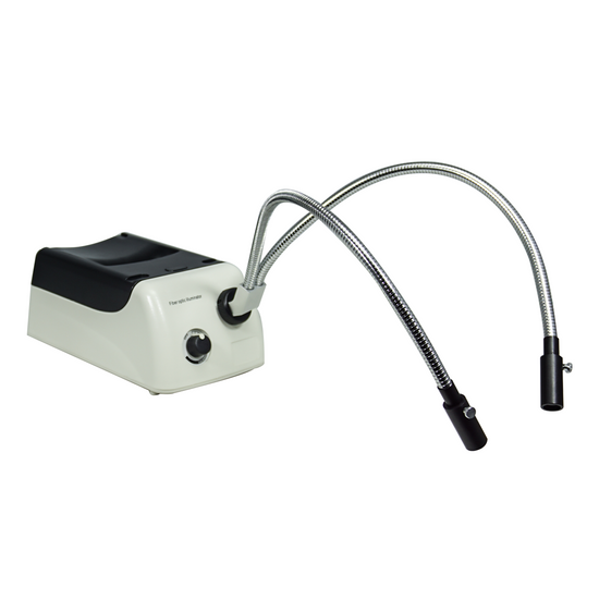
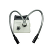
Halogen Light. Light Adjustable. Fiber Cable Adapter Size: 5/8 in. End Adapter. Pointer Panel Meter/Scale. Replacement Bulb: BU99032301. Filter Color: Light Blue. Filter Size: Dia. 30mm. Gooseneck Dual Pipe Light . Fiber Cable Output Port Adapter Size: Dia. 8mm. Fiber Cable Input Port Adapter Size: 5/8 in. End Adapter. Optical Fiber Cable Length: 460mm. Output Power: 150W. Input Voltage: AC 90-240V 50/60Hz. Output Voltage: DC 21V. Power Cord Connector Type: USA 3 Pins.
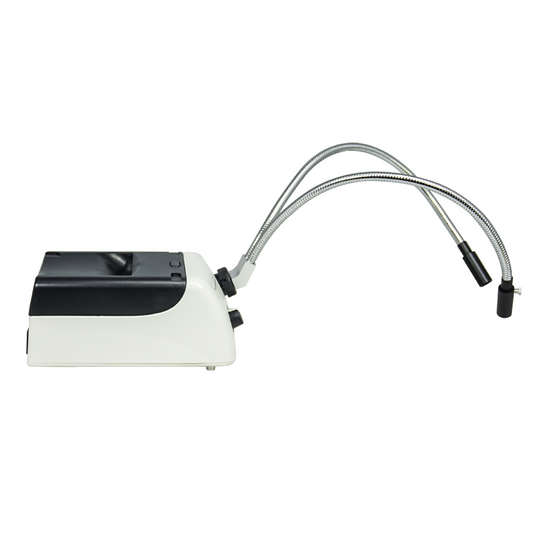
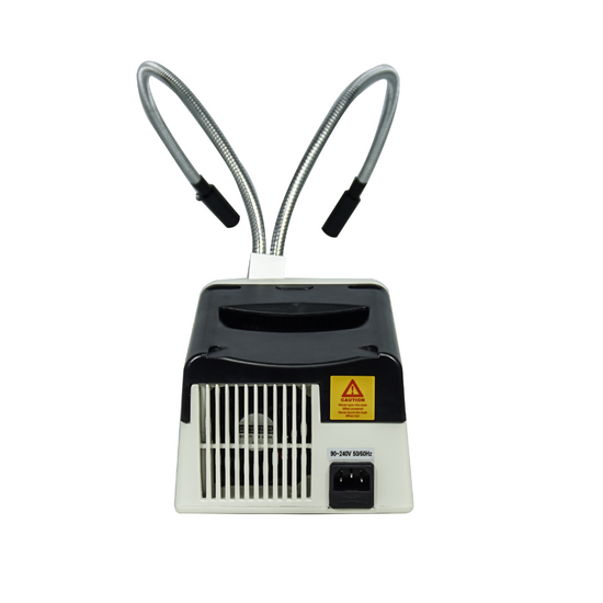
ML02311113 150W Fiber Optic Illuminator (Kit)
Color Filter
| Filter (Blue) | |
| Filter Color | Light Blue |
| Filter Size | Dia. 30mm |
| Filter Switch Type | Plug Type |
| Material | Glass |
| Net Weight | 0.01kg (0.02lbs) |
Fiber Optic Light Source
| 150W Fiber Optic Illuminator | |
| Light Source Type | Halogen Light |
| Power Supply Adjustable | Light Adjustable |
| Power Box Light Port | Single Hole |
| Fiber Cable Adapter Size | 5/8 in. End Adapter |
| Power Box Panel Meter Display | Pointer Panel Meter/Scale |
| Power Box Cooling System | Fan Cooling system |
| Power Box Dimensions | 260x160x125mm |
| Replacement Bulb | BU99032301 |
| Output Power | 150W |
| Input Voltage | AC 90-240V 50/60Hz |
| Output Voltage | DC 21V |
| Power Cord Connector Type | USA 3 Pins |
| Power Cable Length | 1.8m |
| Material | Plastic |
| Color | White |
| Net Weight | 1.77kg (3.90lbs) |
Optical Fiber Light Guide
| 460mm Dual Pipe Light Guide | |
| Optical Fiber Cable Type | Gooseneck Dual Pipe Light |
| Fiber Light Output Port Size | Dia. 5mm |
| Fiber Cable Output Port Adapter Size | Dia. 8mm |
| Fiber Light Input Port Size | Dia. 7mm |
| Fiber Cable Input Port Adapter Size | 5/8 in. End Adapter |
| Pipe Material | Gooseneck Fiber Cable |
| Optical Fiber Cable Length | 460mm |
| Pipe Diameter | Dia. 12.4mm |
| Pipe Color | Silver |
| Flexural Property | Min. Bending Radius ≥30D |
| Fiber Cable Mounting Type | Fastening Screw |
| Fiber Condenser Light Spot Adjustable | Adjustable |
| Material | Metal |
| Color | Silver |
| Net Weight | 0.60kg (1.32lbs) |
Technical Info
Instructions
IlluminatorClose Λ
| The conditions of different illumination of the microscope are a very important parameter. Choosing the correct illumination method can improve the resolution and contrast of the image, which is very important for observing the imaging of different objects. The wavelength of the light source is the most important factor affecting the resolution of the microscope. The wavelength of the light source must be smaller than the distance between the two points to be observed in order to be distinguished by the human eye. The resolution of the microscope is inversely proportional to the wavelength of the light source. Within the range of the visible light, the violet wavelength is the shortest, providing also the highest resolution. The wavelength of visible light is between 380~780nm, the maximum multiple of optical magnification is 1000-2000X, and the limit resolution of optical microscope is about 200nms. In order to be able to observe a much smaller object and increase the resolution of the microscope, it is necessary to use light having a much shorter wavelength as the light source. The most commonly used technical parameters for describing illumination are luminescence intensity and color temperature. Luminescence intensity, with lumen as unit, is the physical unit of luminous flux. The more lumens, the stronger the illumination. Color temperature, with K (Kelvin) as unit, is a unit of measure indicating the color component of the light. The color temperature of red is the lowest, then orange, yellow, white, and blue, all gradually increased, with the color temperature of blue being the highest. The light color of the incandescent lamp is warm white, its color temperature is 2700K, the color temperature of the halogen lamp is about 3000K, and the color temperature of the daylight fluorescent lamp is 6000K. A complex and complete lighting system can include a light source, a lampshade or lamp compartment, a condenser lens, a diaphragm, a variety of wavelength filters, a heat sink cooling system, a power supply, and a dimming device etc. Select and use different parts as needed. Of which, selection and use of the illuminating light source is the most important part of the microscope illumination system, as and other components are designed around the illuminating wavelength curve and characteristics of the illuminating light source. Some of the microscope light sources are pre-installed on the body or frame of the microscope, and some are independent. There are many types and shapes of light sources. Depending on the requirements of the microscope and the object to be observed, one type or multiple types of illumination at the same time can be selected. In addition, the whole beam and band adjustment of the light source, the position and illumination angle of the light source, and the intensity and brightness of the light all have a great influence on the imaging. For microscope imaging, a good lighting system may be a system that allows for more freedom of adjustment. In actual work, such as industry, too many adjustment mechanisms may affect the efficiency of use, therefore choose the appropriated configured lighting conditions is very important. |
Color FilterClose Λ
| Color filter is a type of filter that allows light of only a certain wavelength and color range to pass, while light of other wavelengths is intercepted. Color filter is made of colored glass, and it has various bandwidths and color for selection. Both artificial light source (lamp light) and natural light (daylight) are all full-color light, including seven colors, namely, red, orange, yellow, green, blue, indigo and purple. As the microscope illumination, different types of light sources have different color temperatures and brightness. In order to adjust the color of the light source, it is necessary to install a filtering device at the light exit port of the light source, so that the spectrum of a certain wavelength band is transmitted or blocked. Color filter generally can only be added to the illumination path to change the color of the illumination source and improve the contrast of the image, but generally it is not installed in the imaging path system, which affect the image quality. There are many types of color filters. In addition to the color requirements, color filters of different colors also contribute to the imaging quality. Color filters using the same color will brighten the color of the image. Of the traditional daylight filter, there are relatively more red and yellow light in the lamp light, the resolution is not high, and the observation is not comfortable. The use of daylight filter can absorb the color between yellow to red spectrum emitted by the light source, thus the color temperature becomes much closer to daylight, making microscope observation more comfortable, and it is one of the most used microscope color filters. Daylight blue filter can get close to the daylight spectrum, obtain more short-wave illumination, and improve the resolution of the objective lens. For example, using blue color filter (λ=0.44 microns) can improve the resolution by 25% than green color filter (λ=0.55 microns). Therefore, blue color filter can improve the resolution, and improve the image effect observed under the microscope. However, the human eye is sensitive to green light with a wavelength of about 0.55 microns. When using blue color filters for photomicrography, it is often not easy to focus on the projection screen. Yellow and green filters: both yellow and green filters can increase the contrast (i.e. contrast ratio) of details of the specimen. As far as the achromatic objective lens is concerned, the aberrations in the yellow and green bands are better corrected. Therefore, when yellow and green color filters are used, only yellow and green light passes, and the aberration will be reduced, thereby improving the imaging quality. For semi-apochromatic and apochromat objectives, the focus of visible light is concentrated. In principle, any color filter can be used, but if yellow and green filters are used, the color will make the human eye feel comfortable and soft. Red filter. Red has the longest wavelength and the lowest resolution in visible light. However, red light image can filter and eliminate the variegated background in the image. Therefore, so it has a very good effect for some applications that do not require color features for identification, and the edges and contours of the image are also the clearest, which is more accurate for measurement. Medium gray filters, also known as neural density filters, or ND for short, can uniformly reduce visible light. It is suitable for photomicrography and connection to computer monitors for observation. ND can be used for exposure control and good light absorption, and reduce the light intensity while not changing the color temperature of the microscope light source. |
Fiber Optic Light SourceClose Λ
| Fiber optic light source refers to an illuminating light source that does not contain or contains less spectrum of infrared heat radiation in a illuminating or light guiding body, for example, the popular LED light source, which is a typical illuminator fiber optic light source. In microscopic illumination, the optical fiber cold light source (commonly referred to as “cool light”) means that, after the illumination beam is transmitted through the optical fiber of the light guide body, the heat radiation is not brought to the light exit port, thereby achieving "cold light" effect. The portion of the illuminating light source of the optical fiber has been conventionally illuminated with a halogen light source. In recent years, high-power LED lighting has been widely used. Although the bulb of halogen light source can generate a lot of heat radiation, because of its high brightness when emitting light, it belongs to full-band light, with good color reproduction and comfortable observation by human eye, and therefore is still irreplaceable in some applications. Luminous light sources usually require a high-power light source to achieve strong light, therefore heat dissipation is very important. Whether it is a halogen light source or an LED light source, fan cooling is usually adopted. Fiber optic lighting application has many advantages: 1. The thermal conductivity of the optical fiber is poor. When the light source (light bulb) emits light, the thermal radiation, after being separated by the optical fiber, is not transmitted to the object to be observed. So, while maintaining the wavelength and brightness of the light, it becomes "cold light". When using strong light, cold light may not damage the observed objects, especially in medical and biological applications. 2. Single light source can be transmitted through the optical fiber, and at the same time there are multiple light-emitting points with the same light-emitting characteristics. The light-emitting port can be arranged at different positions and angles, or made into different shapes, such as double-branch lighting, ring lighting, multi-point lighting etc. 3. The light source host and the light exit port illumination point are transmitted through the optical fiber, and therefore the host can be placed in a safe or suitable position without affecting the illumination position of the light exit port, so that there will be more flexibility in design and use. 4. The light exiting port illumination point is transmitted through the optical fiber, and it can filter freely the wavelength of the light at the light source position in the front end of the light entrance, increase the polarization effect, and adjust the brightness and darkness. For example, improve the contrast and contrast ratio of the details of the object to be observed through various color filters, filter out the ultraviolet and infrared light, and reduce damage to certain items.. 5. In the light source host and optical fiber used in fiber optic lighting, the service life of the optical fiber can be decades, and the design separating the light source from the optical fiber makes the light source easy to repair and replace. |
Light AdjustableClose Λ
| The brightness of the light source adjustable is very important in the imaging of the microscope. Since the difference of the numerical aperture of the objective lens of high magnification and low magnification is very big, more incident light is needed to achieve a much better resolution when using a high magnification objective lens. Therefore, when observing through a high magnification objective lens, the brightness required is high; when observing through a low magnification objective lens, the brightness required is low. When observing different objects, or feature points of the same object at different positions, the brightness needs are also different; including the difference of background light or reflection within the field of view of observation, it has a great influence on the effect of observing the object, and therefore one needs to adjust the brightness of the light source according to each object to be observed. In the light source capable of providing continuous spectrum, such as a halogen lamp, the brightness adjustment of the light not only adjusts the brightness and intensity of the light, but also changes the spectrum emitted by the light source. When the light source is dark, there are many components of red light, and when the brightness is high, there are more blue spectrum. If the required light is strong and the spectrum needs to be changed, the light can be kept at a brighter intensity, which is solved by adjusting the spectrum by adding a color filter. Take note of the dimming button on the light source, after the On/Off switch is turned on, normally clockwise is to brighten, and counterclockwise is to darken. If it is adjusted to the lowest brightness, the light source should normally be lit. If the naked eye still can't see the object being illuminated brightly, you need to adjust the brightness knob to a much bigger position. Generally, there is scale marking on the dimming knob, which is an imaginary number representing the percentage of brightness, or an electronic digital display, giving the brightness of the light source under the same conditions a marking. |
Optical Fiber Light GuideClose Λ
| Optical fiber bundle for illumination, is referred to as optical fiber light guide for short. Optical fiber light guide is a fiber core made of transparent material (typically, glass fiber is made of silicon dioxide). Around the fiber core, a cladding layer is formed, using a material having a refractive index lower than that of the fiber core, that is, if the refractive index of the fiber core and the cladding layer are n1 and n2, then n1 must be >n2. The transmission of the optical fiber makes use of the principle of total reflection of light. In this fiber core medium, light is to maintain its characteristics of optical waveform for transmission, wherein the fiber core portion of high refractive index is the main channel for light transmission, while the outer casing of low refractive index covers the entire fiber core. Since the core has a higher refractive index than the outer casing, total reflection occurs, and therefore light can be transmitted in the fiber core. The core of the optical fiber is generally classified into glass fiber, quartz fiber, plastic fiber, and liquid core fiber etc. Microscope illumination usually uses glass fiber, which can have better transmittance for light of different wavelengths. For glass fiber, its optical core material is multi-component optical glass with high refractive index, whereas its cladding material is optical glass with low refractive index. The commonly used multi-component glass formula include: sodium-borosilicate glass (Na-B-Si), potassium-borosilicate glass (K-B-Si), sodium-zinc aluminoborosilicate glass (Na-Zn-Al-B-Si), and the like. Glass fiber, made of optical glass, has a much higher transparency than a ordinary set of glass, but still has a relatively high attenuation value, generally about 1dB/m. The lighting fiber optic wire is very thin, and cannot be bent at a large angle. Generally, its minimum bending radius ≥30D (Min. bending radius ≥30D). Check the breaking of the fiber optic wire, you can use one side section to face the light, and the other side section to see the dark part. If there is too much break, it can’t be repaired, but the entire fiber be replaced. |
PackagingClose Λ
| After unpacking, carefully inspect the various random accessories and parts in the package to avoid omissions. In order to save space and ensure safety of components, some components will be placed outside the inner packaging box, so be careful of their inspection. For special packaging, it is generally after opening the box, all packaging boxes, protective foam, plastic bags should be kept for a period of time. If there is a problem during the return period, you can return or exchange the original. After the return period (usually 10-30 days, according to the manufacturer’s Instruction of Terms of Service), these packaging boxes may be disposed of if there is no problem. |
| Contains | ||||||||||
| Parts Including | ||||||||||
| ||||||||||
| Packing | |
| Packaging Type | Carton Packaging |
| Packaging Material | Corrugated Carton |
| Packaging Dimensions(1) | 32x21x20cm (12.598x8.268x7.874″) |
| Packaging Dimensions(2) | 23x22.5x4cm (9.055x8.858x1.575″) |
| Inner Packing Material | Plastic Bag |
| Ancillary Packaging Materials | Corrugated Carton |
| Gross Weight | 2.80kg (6.17lbs) |
| Minimum Packaging Quantity | 1pc |
| Transportation Carton | Carton Packaging |
| Transportation Carton Material | Corrugated Carton |
| Transportation Carton Dimensions(1) | 32x21x20cm (12.598x8.268x7.874″) |
| Transportation Carton Dimensions(2) | 23x22.5x4cm (9.055x8.858x1.575″) |
| Total Gross Weight of Transportation(kilogram) | 2.80 |
| Total Gross Weight of Transportation(pound) | 6.17 |
| Quantity of One Transportation Carton | 2pc |


