


Quick Overview
Finite. Total Magnification: 30.4-220X. 1X Objective. Standard Coupler: 1X. Zoom Ratio: 1:6.9. Body Mounting Size for Stand: Dia. 76mm. Magnification Detent : 1X per pre-set stop. Objective Converter Angle: 45°. Track Stand. Objective Rotation Angle Motorized. Illumination Type: LED Reflection Light. Top Illumination: Ring Light. CMOS. 2.0 Megapixels. Windows 2000/XP/Vista/7/8/10. Screen Size: 11.6in. Input Voltage: AC 90-265V 50/60Hz. Input Voltage: DC 12V.
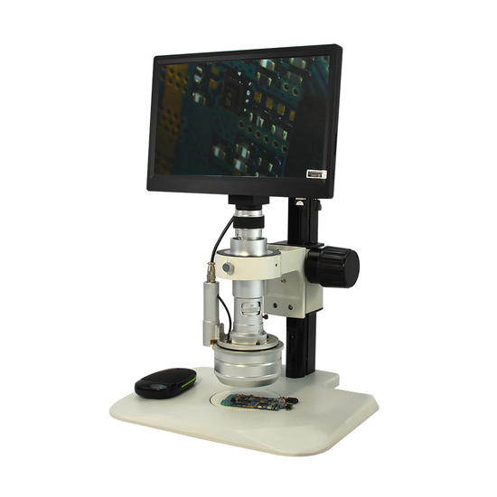
TD02020201 3D Video Microscope
Optical System Specifications
| Optical System | Finite |
| System Optical Magnification | 0.65-4.5X |
| System Electronic Magnification | 46.8X |
| Total Magnification | 30.4-220X |
| Standard Objective | 1X Objective |
| Standard Coupler | 1X |
| System Working Distance | 25-30mm |
Video Monocular Zoom Body
| 3D Video Zoom Body | |
| Body Optical System | Finite |
| Body Magnification | 0.65-4.5X |
| Zoom Range | 0.65-4.5X |
| Zoom Ratio | 1:6.9 |
| Zoom Operating Mode | With the Nosepiece |
| Body Mounting Size for Stand | Dia. 76mm |
| Magnification Detent | 1X per pre-set stop |
| Objective Converter Angle | 45° |
| Magnification of Objective Converter | 1X |
| Objective Converter Rotatable | 360° |
| Objective Converter Operating Mode | Motorized |
| Objective Converter Working Distance | 25-30mm |
| Electric Controller | Objective Rotation Angle Motorized |
| Motor Type | DC Motor |
| Motor Input Voltage | 12V DC |
| Motor Speed | Adjustable |
| Controller Operation Type | Switch |
| Controller Dimensions | 180x110x47mm |
| Illumination Type | LED Reflection Light |
| Top Illumination | Ring Light |
| Top Illumination Type | LED |
| LED Quantity | 30 |
| Adjustable Coupler | Adjustable |
| Coupler Magnification | 1X |
| For Camera Sensor Size | Under 1/3 in. |
| C/CS-Mount Coupler | C-Mount |
| Input Voltage | AC 90-265V 50/60Hz |
| Output Voltage | DC 12V |
| Power Cord Connector Type | USA 3 Pins |
| Power Cable Length | 1.8m |
| Surface Treatment | Electroplating |
| Material | Metal |
| Color | Silver |
| Net Weight | 2.22kg (4.89lbs) |
Track Stand
| 76mm Track Stand | |
| Stand Type | Track Stand |
| Holder Adapter Type | Dia. 76mm Scope Holder |
| Track Length | 325mm |
| Base Type | Table Base |
| Base Shape | Rectangle |
| Stand Throat Depth | 121mm |
| Base Dimensions | 320x305x16mm |
| Focus Mode | Manual |
| Focus Distance | 200mm |
| Coarse Focus Distance per Rotation | 23mm |
| Focusing Knob Tightness Adjustable | Tightness Adjustable |
| Surface Treatment | Spray Paint |
| Material | Metal |
| Color | White |
| Net Weight | 3.10kg (6.83lbs) |
| Dimensions | 320x305x341mm (12.598x12.008x13.425 in. ) |
Microscope Plate
| 95x5mm Black White Plate | |
| Plate Type | Black White Plate |
| Plate Size | Dia. 95x5mm |
| Material | Plastic |
| Color | Black, White |
| Net Weight | 0.04kg (0.09lbs) |
| Applied Field | For ST0201, ST0501, ST1901, ST0801, ST0802 Series Post Stand. ST0203, ST0204 ST0403 Series Track Stand |
LCD Display Digital Camera
| 11.6 in. LCD Display Digital Camera | |
| Image Sensor | CMOS |
| Image Sensor Size | 1/2.86 in. |
| Image Sensor Diagonal size | 6.592mm (0.260 in. ) |
| Camera Maximum Pixels | 2.0 Megapixels |
| Camera Resolution | 1920x1080 |
| Camera Lens Mount | CS-Mount |
| Transmission Frame Rate | 36fps |
| White Balance | Manual/Auto |
| Gain Control | Adjustable |
| Exposure Control | Manual/Auto |
| Camera Crosshairs | Cross Line |
| Number of Crosshairs | 4 Movable Crosshairs |
| Line Color | User Defined |
| Image Capture Output Format | TIFF/JPG/BMP/PNG |
| Video Output Format | MP4 |
| System Requirement | Windows 2000/XP/Vista/7/8/10 |
| Driver Installation | Driver free |
| Camera Housing Material | Plastic |
| Camera Housing Size | 40x40x58mm |
| Camera Housing Color | Black |
| Max. Supported Memory Card | 32G |
| Screen Size | 11.6in |
| Screen Aspect Ratio | 16:9 |
| Monitor Signal Format | NTSC/PAL Auto-Switch |
| Monitor Max. Resolution | 1080P |
| Screen Backlight | LED Display |
| Input Voltage | DC 12V |
| Net Weight | 0.65kg (1.43lbs) |
| Dimensions | 280x200x55mm (11.024x7.874x2.165 in. ) |
Camera Accessories
| 11.6 in. LCD Display Digital Camera | |
| C/CS Spacer | 5mm |
| Mouse Operation | Yes |
| Memory Type | SD |
| Memory Capacity | 4G |
Other Parameters
| Surface Treatment | Electroplating |
| Material | Metal |
| Color | Silver |
| Net Weight | 6.15kg (13.59lbs) |
| Dimensions | 320x305x341mm (12.598x12.008x13.425 in. ) |
| This Kit Includes | TD07011101, ST02031102, DC43511111, SA02081207 |
Series
| TD0202 | TD02020201 |
Technical Info
Instructions
Digital MicroscopeClose Λ
| Digital microscope is the general term for microscope that can convert an optical image into a digital image, and usually does not specifically refer to a certain type of microscope. It should be noted however that most microscopes can be mounted with cameras and display devices to change to digital microscope. Microscopes in the visible range, from the digital imaging point of view, all use CCD or CMOS sensors to image the optical signal as an electric signal on a computer or display. However, the difference between various kinds of digital microscopes mainly comes from the optical microscope itself, so it is necessary to look at the imaging effect and function of the optical part in order to select the type of digital microscope. From the classification point of view, digital microscopes can be divided into: digital biological microscopes, digital stereo microscopes, etc. It should be noted that due to the variety of lenses, ordinary lenses or microscopes, if mounted with a digital camera, can all become a digital microscope. At present, the trend of digital microscopes is not only to present simple digital images, but to collect, process and analyze images through back-end software, especially for image measurement, comparison, judgment, and large-format scanning and splicing, and three-dimensional synthesis and so on, these aspects have been widely developed and applied. |
FiniteClose Λ
| Microscopes and components have two types of optical path design structures. One type is finite optical structural design, in which light passing through the objective lens is directed at the intermediate image plane (located in the front focal plane of the eyepiece) and converges at that point. The finite structure is an integrated design, with a compact structure, and it is a kind of economical microscope. Another type is infinite optical structural design, in which the light between the tube lens after passing the objective lens becomes "parallel light". Within this distance, various kinds of optical components necessary such as beam splitters or optical filters call be added, and at the same time, this kind of design has better imaging results. As the design is modular, it is also called modular microscope. The modular structure facilitates the addition of different imaging and lighting accessories in the middle of the system as required. The main components of infinite and finite, especially objective lens, are usually not interchangeable for use, and even if they can be imaged, the image quality will also have some defects. The separative two-objective lens structure of the dual-light path of stereo microscope (SZ/FS microscope) is also known as Greenough. Parallel optical microscope uses a parallel structure (PZ microscope), which is different from the separative two-object lens structure, and because its objective lens is one and the same, it is therefore also known as the CMO common main objective. |
System Optical MagnificationClose Λ
| The magnification of the objective lens refers to the lateral magnification, it is the ratio of the image to the real size after the original image is magnified by the instrument. This multiple refers to the length or width of the magnified object. System optical magnification is the product of the eyepiece and the objective lens (objective lens zoom set) of the optical imaging part within the system. Optical magnification = eyepiece multiple X objective lens/objective lens set The maximum optical magnification of the microscope depends on the wavelength of the light to which the object is illuminated. The size of the object that can be observed must be greater than the wavelength of the light. Otherwise, the light cannot be reflected or transmitted, or recognized by the human eye. The shortest wavelength of ultraviolet light is 0.2 microns, so the resolution of the optical microscope in the visible range does not exceed 0.2 microns, or 200 nanometers. This size is converted to the magnification of the microscope, and it is the optical magnification of 2000X. Usually, the compound microscope can achieve 100X objective lens, the eyepiece is 20X, and the magnification can reach 2000X. If it is bigger, it will be called "invalid magnification", that is, the image is large, but the resolution is no longer increased, and no more details and information can be seen. |
System Electronic MagnificationClose Λ
| The electronic magnification usually refers to the lateral magnification, that is, the ratio of the magnification of the image of the object being observed after passing through the image sensor and the terminal display. This magnification is the digital image magnification and it does not improve the resolution of the original image to the object being observed. Electronic magnification = display size (diagonal) / camera sensor target (diagonal) (Appendix) Different Camera Sensor Target Diagonal Conversion Table |
Total MagnificationClose Λ
| Total magnification is the magnification of the observed object finally obtained by the instrument. This magnification is often the product of the optical magnification and the electronic magnification. When it is only optically magnified, the total magnification will be the optical magnification. Total magnification = optical magnification X electronic magnification Total magnification = (objective X photo eyepiece) X (display size / camera sensor target ) |
System Working DistanceClose Λ
| Working distance, also referred to as WD, is usually the vertical distance from the foremost surface end of the objective lens of the microscope to the surface of the observed object. When the working distance or WD is large, the space between the objective lens and the object to be observed is also large, which can facilitate operation and the use of corresponding lighting conditions. In general, system working distance is the working distance of the objective lens. When some other equipment, such as a light source etc., is used below the objective lens, the working distance (i.e., space) will become smaller. Working distance or WD is related to the design of the working distance of the objective lens. Generally speaking, the bigger the magnification of the objective lens, the smaller the working distance. Conversely, the smaller the magnification of the objective lens, the greater the working distance. When it is necessary to change the working distance requirement, it can be realized by changing the magnification of the objective lens. |
Video Monocular Zoom BodyClose Λ
| Video monocular zoom body is a zoom body that has only one set of optical paths, and it is also the body of the video continuous zoom. The upper end of the microscope body can be connected to the standard C-interface photo eyepiece, and then connected to the microscope camera; the lower end is the objective lens, and the objective lens of parallel structure is generally separated from the body, whereas the microscope body of finite structure is combined with the objective lens. Some bodies of microscope have also a light source coaxial illumination device. |
Zoom RangeClose Λ
| Zoom in zoom microscope means to obtain different magnifications by changing the focal length of the objective lens within a certain range through adjustment of some lens or lens set while not changing the position of the object plane (that is, the plane of the point of the observed object perpendicular to the optical axis) and the image plane (that is, the plane of the image imaging focus and perpendicular to the optical axis) of the microscope. Zoom range refers to the range in which the magnification is from low to high. In the zoom range of the microscope, there is no need to adjust the microscope knob for focusing, and ensure that the image is always clear during the entire zoom process. The larger the zoom range, the stronger the adaptability of the range for microscope observation, but the image effects at both ends of the low and high magnification should be taken into consideration, the larger the zoom range, the more difficult to design and manufacture, and the higher the cost will be. |
Zoom RatioClose Λ
| Zoom ratio is the ratio of the maximum magnification / the minimum magnification. Expressed as 1: (ratio of maximum magnification / minimum magnification). If the maximum magnification is 4.5X, the minimum magnification is 0.7X, then the zoom ratio = 4.5 / 0.7 = 6.4, the zoom ratio will be 1:6.4. Zoom ratio is obtained by the intermediate magnification group of the microscope. When the magnification is increased or decreased by using other objective lenses, the zoom ratio does not change accordingly. |
With the NosepieceClose Λ
| When the microscope body changes the magnification, it is realized by adjusting the zoom drum or nosepiece. Generally, the lower case of the microscope is used as the zoom drum or nosepiece. When magnification conversion is required, it can be realized by turning the zoom drum or nosepiece. |
Magnification Detent Close Λ
| In the body of zoom microscope, zooming is continuous. When rotating to a certain position, generally an integral multiple, a positioning structure or detent is added, which has a distinct hand feel during the zooming process, and stops at this position. When measuring, or testing by factory for unified standard magnification, a magnification detent device can avoid the error caused by the inaccurate multiple positioning of the optical magnification. |
Motorized Close Λ
| The nosepiece of a microscope is generally switched manually. A motarized nosepiece is to add an electric motor onto the nosepiece to control switching of the nosepiece through the electric switch, so as to switch the objective used. This device can be added when some microscopes are bulky, switching of the objective needs to be kept steady, and needs to be frequently switched. |
Adjustable CouplerClose Λ
| On the coupler/C-mount-adapter, there is an adjustable device to adjust the focal length. |
Coupler MagnificationClose Λ
| Coupler magnification refers to the line field magnification of the coupler/C-mount-adapter. With different magnifications of the adapter lens, images of different magnifications and fields of view can be obtained. The size of the image field of view is related to the sensor size and the coupler/C-mount-adapter magnification. Camera image field of view (mm) = sensor diagonal / coupler/C-mount-adapter magnification. For example: 1/2 inch sensor size, 0.5X coupler/C-mount-adapter coupler, field of view FOV (mm) = 8mm / 0.5 = 16mm. The field of view number of the microscope 10X eyepiece is usually designed to be 18, 20, 22, 23mm, less than 1 inch (25.4mm). Since most commonly used camera sensor sizes are 1/3 and 1/2 inches, this makes the image field of view on the display always smaller than the field of view of the eyepiece for observation, and the visual perception becomes inconsistent when simultaneously viewed on both the eyepiece and the display. If it is changed to a 0.5X coupler/C-mount-adapter, the microscope image magnification is reduced by 1/2 and the field of view is doubled, then the image captured by the camera will be close to the range observed in the eyepiece. Some adapters are designed without a lens, and their optical magnification is considered 1X. |
For Camera Sensor SizeClose Λ
| For the size of the lens field of view of the coupler/C-mount-adapter, in the design process, the size of the camera sensor imaging target should be considered. When the field of view of the lens is smaller than the target plane of the camera, “black border” and “dark corner” will appear. The general microscope coupler/C-mount adapters are generally designed for the 1/2" camera targets. When a camera of 2/3 or larger target is used, the “dark corner” phenomenon will appear in the field of view. Especially, at present, DSLR cameras generally use large target plane design (1 inch full field of view), when used for microscopic photographing, the general DSLR camera coupler/C-mount adapter will have “black border”. Generally, the “dark corner” that appears on the field of view is often that the center of the microscope and the camera are not aligned. Adjust the position of the screw on the camera adapter, or turn the camera adapter to adjust or change the effect. |
C/CS-Mount CouplerClose Λ
| At present, the coupler/C-mount adapter generally adopts the C/CS-Mount adapter to match with the industrial camera. For details, please refer to "Camera Lens Mount". |
Track StandClose Λ
| Throughout the focusing range, the track stand moves up and down along the guide rail through the focusing mechanism to achieve the purpose of focusing the microscope. This kind of structure is relatively stable, and the microscope is always kept moving up and down vertically along a central axis. When the focus is adjusted, it is not easy to shake, and there is no free sliding phenomenon. It is a relatively common and safe and reliable accessory. The size of the stand is generally small, flexible and convenient, and most of them are placed on the table for use, Therefore, together with the post stand, it is also called “desktop or table top stand". With regard to the height of the stand, most manufacturers usually do not make it very high. If the guide rail is long, it is easy to deform, and relatively more difficult . |
Dia. 76mm Scope HolderClose Λ
| The 76mm stand scope holder is the most popular microscope body adapter size, suitable for stereo microscopes produced by most manufacturers. Place the microscope body in a 76mm scope holder, tighten with screws to avoid shaking when the microscope is in use. Because this stand scope holder is very common, some special-sized microscopes can also borrow and use this stand, but only need a specific adapter to connect the microscope body with a diameter of less than 76mm. |
Stand Throat DepthClose Λ
| Stand throat depth, also known as the throat depth, is an important parameter when selecting a microscope stand. When observing a relatively large object, a relatively large space is required, and a large throat depth can accommodate the object to move to the microscope observation center. |
Focusing Knob Tightness AdjustableClose Λ
| Different microscope bodies, different human operations, and different requirements for observation and operation, all require adjustment of the pre-tightening force of the stand that support microscope body. Facing the stand just right, use both hands to reverse the force to adjust the tightness. (face the knob of one side just right, clockwise is to tighten, counterclockwise is to loosen) In general, after long-time use, the knob will be loose, and adjustment is necessary. |
Microscope PlateClose Λ
| According to different objects to be observed, the appropriate platen should be selected. The microscope plate materials include black and white, black and white finish; transparent glass, frosted glass, metal, etc. Standard stands are generally configured with a suitable microscope plate, but different plates may need to be purchased separately. Black and white microscope plate are made of general plastics, and the different backgrounds in black and white make the object more prominent. Finish microscope plate eliminates reflections during observation. Transparent glass plate is used when observing transparent or translucent objects, and the use of transmitted light source is to make the light penetrate the object to be observed as much as possible. Finish glass plate, with its rough glass surface, can make the transmitted light more uniform and create a diffusing effect, avoiding exposure of the light shadow of the filament directly onto to the observed object. Metal plate, relatively more solid, is more suitable when it is necessary to operate and cut. Microscope plate is generally round shaped, on one side of the base there is a spring clip. When installing, align the plate with the clamp and push it in, and then press down the other end, so that the plate is smoothly embedded in to the circular card slot of the bottom plate. When removing, grab the other end of the clip, push and lift up the plate. |
LCD Display Digital CameraClose Λ
| LCD display digital camera is a combination of a digital camera and a display. |
CMOSClose Λ
| CMOS, or complementary metal oxide semiconductor. Both CMOS and CCD sensors have their own respective advantages and disadvantages. As a kind of photoelectric conversion sensor, among the current cameras, CMOS is relatively more widely used. |
 |
Image Sensor SizeClose Λ
| The size of the CCD and CMOS image sensors is the size of the photosensitive device. The larger the area of the photosensitive device, the larger the CCD/CMOS area; the more photons are captured, the better the photographic performance; the higher the signal-to-noise ratio, the larger the photosensitive area, and the better the imaging effect. The size of the image sensor needs to match the size of the microscope's photographic eyepiece; otherwise, black borders or dark corners will appear within the field of view of observation. |
Camera Maximum PixelsClose Λ
| The pixel is determined by the number of photosensitive elements on the photoelectric sensor of the camera, and one photosensitive element corresponds to one pixel. Therefore, the more photosensitive elements, the larger the number of pixels; the better the imaging quality of the camera, and the higher the corresponding cost. The pixel unit is one, for example, 1.3 million pixels means 1.3 million pixels points, expressed as 1.3MP (Megapixels). |
Camera ResolutionClose Λ
| Resolution of the camera refers to the number of pixels accommodated within unit area of the image sensor of the camera. Image resolution is not represented by area, but by the number of pixels accommodated within the unit length of the rectangular side. The unit of length is generally represented by inch. |
 |
Camera Lens MountClose Λ
| Industrial camera adapters are usually available in three types: 1. C-Mount: 1" diameter with 32 threads per inch, flange back intercept 17.5mm. 2. CS-Mount: 1" diameter with 32 threads per inch, flange back intercept 12.5mm. CS-Mount can be converted to a C-Mount through a 5mm spacer, C-mount industrial camera cannot use the CS-mount lens. 3. F-Mount: F-mount is the adapter standard of Nikon lens, also known as Nikon mouth, usually used on large-sized sensor cameras, the flange back intercept is 46.5mm. |
Transmission Frame RateClose Λ
| Frame rate is the number of output of frames per second, FPS or Hertz for short. The number of frames per second (fps) or frame rate represents the number of times the graphics process is updated per second. Due to the physiological structure of the human eye, when the frame rate of the picture is higher than 16fps, it is considered to be coherent, and high frame rate can make the image frame more smooth and realistic. Some industrial inspection camera applications also require a much higher frame rate to meet certain specific needs. The higher the resolution of the camera, the lower the frame rate. Therefore, this should be taken into consideration during their selection. When needing to take static or still images, you often need a large resolution. When needing to operate under the microscope, or shooting dynamic images, frame rate should be first considered. In order to solve this problem, the general industrial camera design is to display the maximum frame rate and relatively smaller resolution when viewing; when shooting, the maximum resolution should be used; and some cameras need to set in advance different shooting resolutions when taking pictures, so as to achieve the best results. |
White BalanceClose Λ
| White balance is an indicator that describes the precision of white color generated in the image when the three primary colors of red, green and blue are mixed, which accurately reflects the color condition of the subject. There are manual white balance and automatic white balance. White balance of the camera is to "restore white objects to white color under any light source." The chromatic aberration phenomenon occurred under different light sources is compensated by enhancing the corresponding complementary color. Automatic white balance can generally be used, but under certain conditions if the hue is not ideal, options of other white balance may be selected. |
Camera CrosshairsClose Λ
| Camera crosshairs refers to the preset reference line within the camera, which is used to calibrate various positions on the display. The most commonly used is the crosshair, which is to determine the center position of the camera image, and it is very important in measurement. Some cameras also have multiple crosshairs that can be moved to quickly detect and calibrate the size of the object being viewed. Some crosshairs can also change color to adapt to different viewing backgrounds. |
PackagingClose Λ
| After unpacking, carefully inspect the various random accessories and parts in the package to avoid omissions. In order to save space and ensure safety of components, some components will be placed outside the inner packaging box, so be careful of their inspection. For special packaging, it is generally after opening the box, all packaging boxes, protective foam, plastic bags should be kept for a period of time. If there is a problem during the return period, you can return or exchange the original. After the return period (usually 10-30 days, according to the manufacturer’s Instruction of Terms of Service), these packaging boxes may be disposed of if there is no problem. |
Optical Data
| Video Microscope Optical Data Sheet | ||
| P/N | Objective | Coupler |
| TD07011101 (1X) | ||
| Magnification | ||
| TD07011101 | 1X | 0.65-4.5X |
| 1. Magnification=Objective Optical Magnification * Body Magnification * Coupler Magnification | ||
| Camera Image Sensor Specifications | |||
| No. | Camera Image Sensor Size | Camera image Sensor Diagonal | |
| (mm) | (inch) | ||
| 1 | 1/4 in. | 4mm | 0.157" |
| 2 | 1/3 in. | 6mm | 0.236" |
| 3 | 1/2.8 in. | 6.592mm | 0.260" |
| 4 | 1/2.86 in. | 6.592mm | 0.260" |
| 5 | 1/2.7 in. | 6.718mm | 0.264" |
| 6 | 1/2.5 in. | 7.182mm | 0.283" |
| 7 | 1/2.3 in. | 7.7mm | 0.303" |
| 8 | 1/2 in. | 8mm | 0.315" |
| 9 | 1/1.9 in. | 8.933mm | 0.352" |
| 10 | 1/1.8 in. | 8.933mm | 0.352" |
| Digital Magnification Data Sheet | ||
| Image Sensor Size | Image Sensor Diagonal size | Monitor |
| Screen Size (11.6in) | ||
| Digital Zoom Function | ||
| 1/2.86 in. | 6.592mm | 44.7 |
| 1. Digital Zoom Function= (Screen Size * 25.4) / Image Sensor Diagonal size | ||
| Microscope Optical and Digital Magnifications Data Sheet | ||||||||||
| Objective | Coupler | Camera | Monitor | Video Microscope Optical Magnifications | Digital Zoom Function | Total Magnification | Field of View (mm) | |||
| PN | Magnification | PN | Magnification | Image Sensor Size | Image Sensor Diagonal size | Screen Size | ||||
| TD07011101 | 1X | TD07011101 | 1X | 1/2.86 in. | 6.592mm | 11.6in | 0.65-4.5X | 44.7 | 29.06-201.15X | 1.46-10.14mm |
| 1. Video Microscope Optical Magnifications=Objective Optical Magnification * Body Magnification * Coupler Magnification | ||||||||||
| 2. Digital Zoom Function= (Screen Size * 25.4) / Image Sensor Diagonal size | ||||||||||
| 3. Total Magnification= Video Microscope Optical Magnifications * (Screen Size * 25.4) / Image Sensor Diagonal size | ||||||||||
| 4. Field of View (mm)= Image Sensor Diagonal size / Video Microscope Optical Magnifications | ||||||||||
| Contains | ||||||||||
| Parts Including | ||||||||||
| ||||||||||
| Desiccant Bag | 1 Bag | |||||||||
| Allen Key | M2.5 1pc M4 1pc | |||||||||


| Packing | |
| Packaging Type | Carton Packaging |
| Packaging Material | Corrugated Carton |
| Packaging Dimensions(1) | 32x24x38cm (12.598x9.449x14.961″) |
| Packaging Dimensions(2) | 38x36x19cm (14.961x14.173x7.480″) |
| Packaging Dimensions(3) | 33x24.5x9cm (12.992x9.646x3.543″) |
| Packaging Dimensions(4) | 10.5x5.5x13cm (4.133x2.165x5.118″) |
| Inner Packing Material | Plastic Bag |
| Ancillary Packaging Materials | Styrofoam |
| Gross Weight | 8.35kg (18.41lbs) |
| Transportation Carton | Carton Packaging |
| Transportation Carton Material | Corrugated Carton |
| Transportation Carton Dimensions(1) | 32x24x38cm (12.598x9.449x14.961″) |
| Transportation Carton Dimensions(2) | 38x36x19cm (14.961x14.173x7.480″) |
| Transportation Carton Dimensions(3) | 33x24.5x9cm (12.992x9.646x3.543″) |
| Transportation Carton Dimensions(4) | 10.5x5.5x13cm (4.133x2.165x5.118″) |
| Total Gross Weight of Transportation(kilogram) | 8.35 |
| Total Gross Weight of Transportation(pound) | 18.41 |


